The Apple II Europlus uses 4116 type RAM ICs.
On my board, there were about 4 different manufacturers and speeds - obviously some have failed in the past and have been replaced. Without a booting machine however, how can I test that the RAM is working OK?
Thankfully, a circuit for testing 4164 ICs can be used, as long as you can supply the required 12v and -5v power lines that the 4116 ICs require. An Arduino is required.
The 4164 tester instructions I followed are here
The pinout of the 4116s:
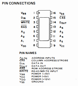
As you can see, pin 1 requires a -5v supply, pin 8 a +12v supply, Pin 9 a +5v supply and pin 16 a ground supply.
Here is the original diagram:
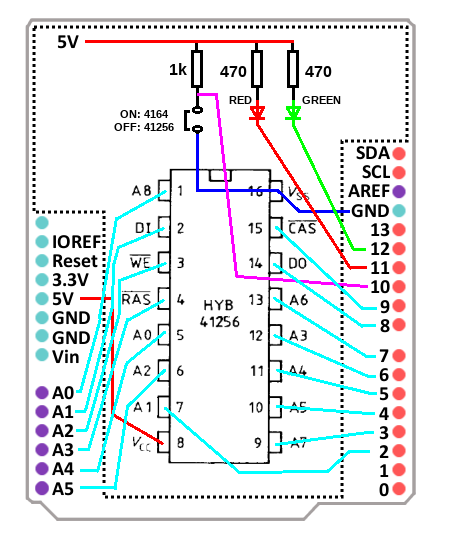
The original pinouts shown Pin 1 being connected to A0 on the Arduino. In our circuit, this must be a -5v supply, so was changed. A0 on the Arduino was left disconnected. The diagram shows Pin 8 on the 41256 IC going to the 5V rail. This was replaced with the 12v supply that the 4116 requires. Pin 9 "A7" on the larger IC is connected to Digital 3 on the original diagram. I connected this to the 5v supply.
4116 Pin 1  > VBB   > -5v Supply
4116 Pin 2  > DIN   > Arduino A1
4116 Pin 3  > WRITE > Arduino A2
4116 Pin 4  > RAS   > Arduino A3
4116 Pin 5  > A0    > Arduino A4
4116 Pin 6  > A2    > Arduino A5
4116 Pin 7  > A1    > Arduino D2
4116 Pin 8  > VDD   > +12v Supply
4116 Pin 9  > VCC   > +5v Supply
4116 Pin 10 > A5    > Arduino D4
4116 Pin 11 > A4    > Arduino D5
4116 Pin 12 > A3    > Arduino D6
4116 Pin 13 > A6    > Arduino D7
4116 Pin 14 > DOUT  > Arduino D8
4116 Pin 15 > CAS   > Arduino D9
4116 Pin 16 > VSS   > Ground (from Apple II PSU)
Where to find a suitable power supply? Well - the Apple II power supply has been recently serviced, and the filter capacitor changed - so we can use this.
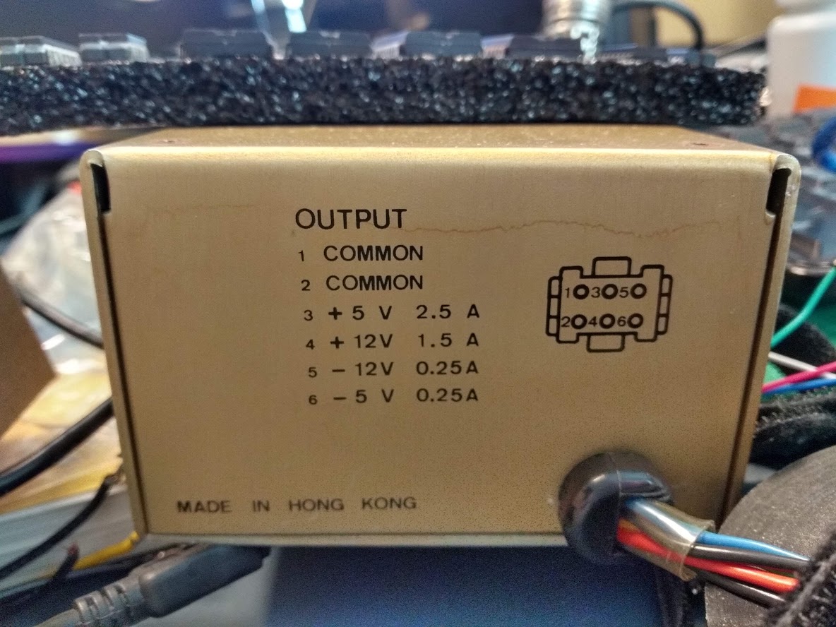
I built the circuit in two sections - power and logic. This way, I could more easily break out the necessary power lines. I first attempted to use just the 12v and ground lines from the PSU, and use the -5v rail on a breadboard power supply, but this resulted in many tested ICs failing. I was sure that 20+ ICs could not be faulty, so rearranged the circuit to run completely from the Apple II PSU, save for the Ardunio which is powered by the USB connection.
In the photo below you can see the 5v, -5v, 12v and Ground lines being fed to a 4116 being tested.
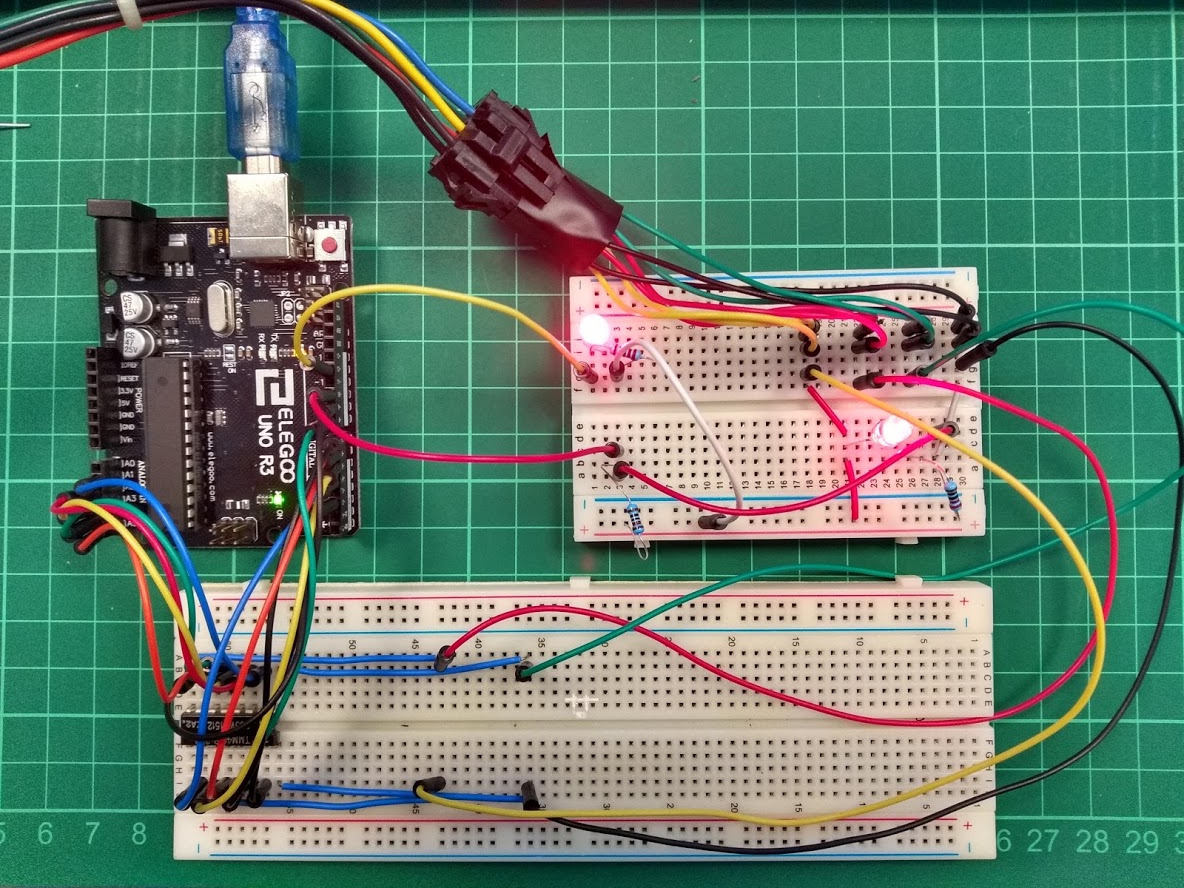
The two LEDs show either the test progress (this is the "green" LED from the instructions) and the status of the Apple II PSU.
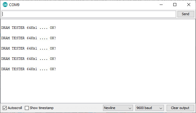
No changes were made to the Arduino project code.
Some ICs tested OK (32 out of the stock that I have)
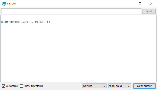
Some not so OK (8 of the stock):
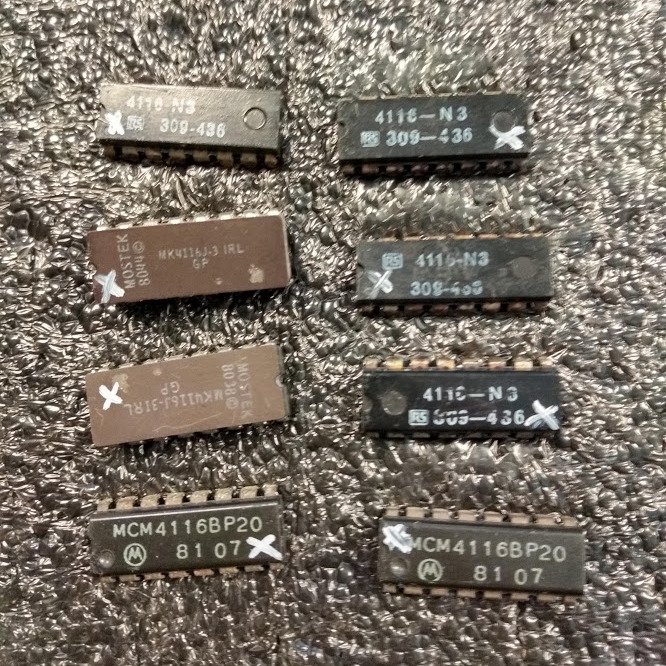
The OK ICs I marked with a small dot with a Uni Paint Marker, the bad with an X.

I ended up with a small selection of duff ICs for the bin.
Sadly, even with good, tested RAM, the Europlus still does not boot. Back to the drawing board once more.